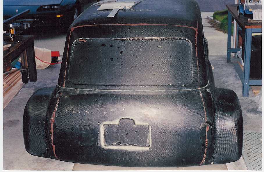
Summer 1996. Here's the shell fresh out of the mold, borrowed to make sure everything was going to fit inside. Yes, it's carbon.
December 1997. Much time had gone by while all the research, chassis, and suspension design was completed. Since safety was a huge consideration all during design (this thing could kill me,) it's going to be a bit heavier than it would be if it were solely a track car, but that's the way it goes. Anyway, I was forced into making a wood mockup and I thought, what a waste of time. Boy was I wrong; with all the changes, I'd still be running in circles had I gone straight to steel. Fit-up was to make absolutely sure the outside dimensions of the future steel chassis would fit within the constraints of the composite shell. It is much easier to change things in wood. (Thanks Cecil!)

Summer 1998. The engine was the first component on the table. It had to be propped up at the proper height and oriented so as the frame was built around it, everything would be in the right place. Note the obligatory coffee can, essential to any home project.
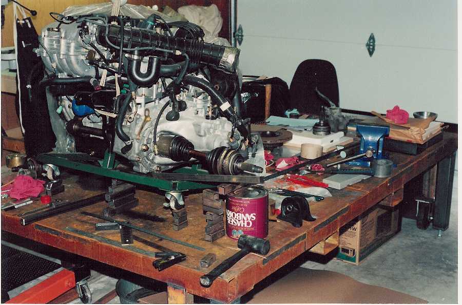
Axle alignment. Slight droop is because the chassis will squat under acceleration, aligning the axle when most needed (probably should have made it more.) If you look closely at the half-shaft, you can see a couple of dings. That's because the bonehead mechanic held it in a steel-jaw vice - if the half shaft breaks, guess where the crack will start.

The wood mockup was completed as much as possible within the shell, and it was time to move it to the table and start attaching things. Once in the correct relative location to the engine, it was clamped down, and mockup construction continued around the drivetrain.

Summer 1999. Wood mockup nearly complete. Checking for interferences between suspension links, tires, and chassis.

Rear end and undertray. I used the reverse technique of fixing a point in space, then built brackets as needed. Here the rear suspension arm pick up points are hard mounted to the table, and brackets will be built out from the tubes to meet the suspension pivots, ensuring the pick up points are accurate. The wedge-shape plywood sections are to determine where the downforce-producing tunnels turn upward.

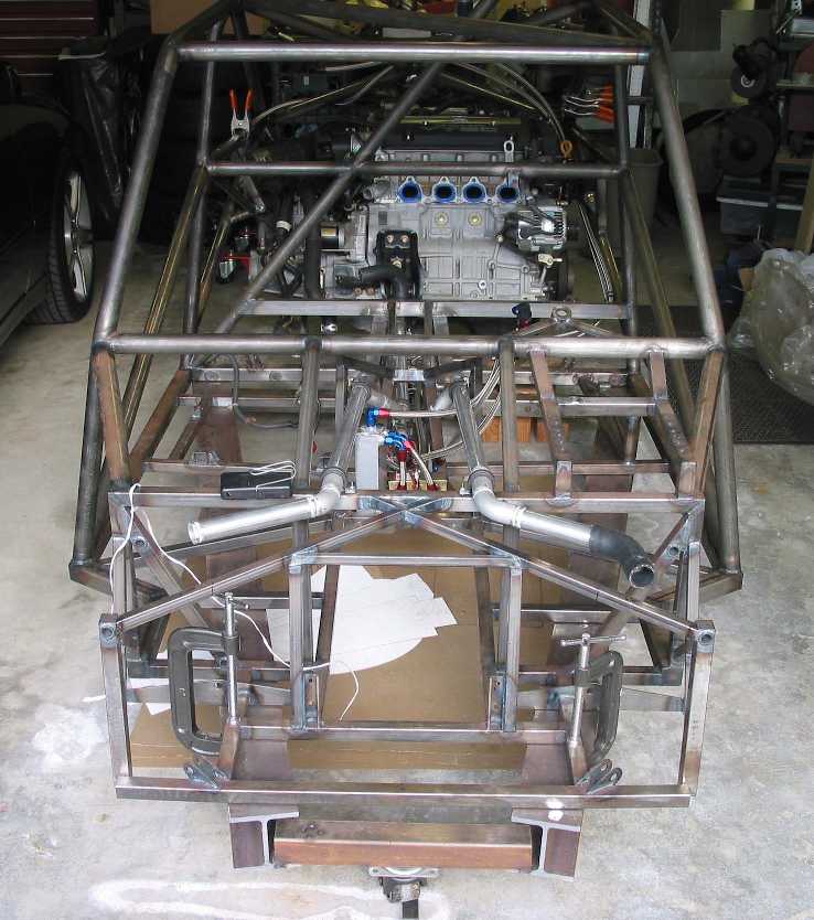
Starting the foot-well. The red box is a 10-gallon fuel cell, positioned in the safest place in the car, where a traditionally mounted transmission goes. The thinking is, if it gets crunched there, I won't have much to worry about by the time the "crunching" gets to the cell. I once saw a horrific racecar fire and have no desire to experience that, hence a real fuel cell instead of a weenie aluminum box. The pedal cluster is perched at the top of the foot-well, and at the bottom is part of the Triumph steering rack. It's funny how many kit cars use this very rack. I wasn't looking for it specifically, just walked around the junkyard looking for a manual rack that would work... and there it was.

Positioning of front components. Radiator air exits upward and out the top of the hood, keeping air from going under the car, which increases downforce. Besides a functioning hood vent looks cool! If the top exit doesn't cool well enough, front wheel well vents will be added, another low-pressure area.

Spring 2000. Complete wood mockup.

The beginnings of the steel chassis. In a way, this was the beginning of the "fun part." All the tough design decisions were made, so now my hat was switching from Designer to Fabricator. As many times through the project, the actual components are used as templates for the chassis, essentially building the chassis in reverse, *away* from the components. You can never have too many rulers... Having a stretched string indicating true center saved me many times from making a "bent car."

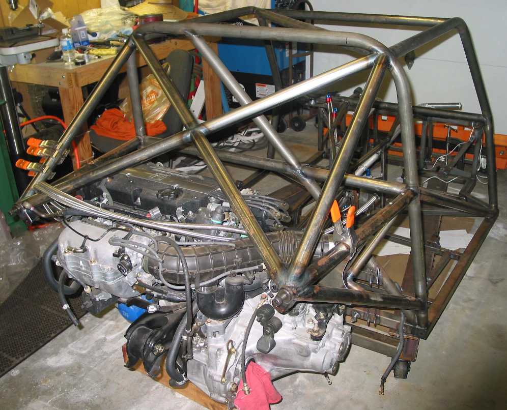
Further chassis progression. What's with the huge tubing? For it's expected weight of 1300lbs, SCCA rules dictate 1.5", 0.090 wall tubing. The rear bulkhead with the diagonal will be double-skinned, probably in stainless on the engine side because of its insulating properties (stainless insulates twice as well as aluminum.) Insulating material will be placed in between to try to keep the interior cool and quiet. Just because it's going to be fast doesn't mean it has to be hot and noisy.

Another angle of the steel frame. About this time 9/11 happened, I took off several months to think about life in general... about what's really important.

Winter 2001. Drilling the stainless floor pan for rivets. The idea was to drill the floor panels now, because later they would be hard to access once the chassis was off the table. Once the components start getting bolted to the chassis, the weight would make it tough to roll over.

First stainless steel floor panel in place. For some reason, a panel full of Clecos looks really cool. Why wasn't aluminum used? If this were a true racecar aluminum would be first choice. But on the street means the floor will be subjected to all sorts of torture from gravel, rocks, dragged over speed bumps, who knows what. I wondered if the panels should be welded on, but people smarter than I said to rivet them. Okay.

Why it's Much easier to work on the floor now rather than after the engine's installed...

More components in place. Here you see the fuel cell, one front rocker arm, and part of one shock. Aluminum coolant lines lead to the radiator.

The first of several tanks. This is the fuel accumulator and pumps, located roughly below where the shifter will go. There are two fuel pickups at the back corners of the cell, so the fuel will be there under acceleration and cornering. The pickups feed two low-pressure pumps that feed the accumulator, always keeping it full. Any extra fuel (or bubbles) rise to the top of the tank and feedback through a small orifice to the cell. At the bottom of the accumulator is the feed to the high pressure pump and filter. The high pressure filter is downstream of the pump so as it starts to clog, the pump won't cavitate. Return fuel from the engine will probably go to the fuel cell, to be used as a heat sink.

Coolant swirl pot, to de-aerate the coolant. Positioned ahead of the engine on the firewall. As the coolant heads out of the engine toward the radiator it passes through this tank. Any bubbles rise to the top and are returned to the main header tank through a small bleeder tube.

Coolant accumulator, mounted high on the passenger-side firewall. Several stubs are to run breather lines wherever needed. One is left in case I need to have a constant bleed from the top of the radiator. Welding aluminum is cool... as long as it's thicker than about 0.040" thick.

Thanks to Ray for suggesting the "Home Powder-Coat System" from Eastwood. It works great as long as you have a large enough electric oven.

Engine stand/dolly - Costco - $80, less than the parts to build one. With this, the engine can be easily moved around the garage, and raised when installing or removing the engine. The cradle connects only to the engine, allowing the transmission to be removed separately.

Spring 2002. A big day, finally moving the chassis off the table after nearly, what, three years? Showing the coolant pipes and part of the fuel system. At the front on either side of the center tunnel are two brackets to which the steering rack bolts. Placing those brackets just right was a big pain in the butt but necessary to avoid bump steer.
A rear view showing the over-hung engine mounts. Missing is the engine under-tray that bolts at the base of the main hoop and to the two bolts at the rear of the triangulation.
Electrical. I was in dire need of a psychological accomplishment, like hearing the engine run! It didn't matter how long it ran, but I wanted to hear it. But before that could happen, all the wiring had to be gone through, removing unneeded connectors, and accounting for all the wires that still had to go someplace. There's no better way to intimately know your car than to go through every single wire in the harness.

Memorial Day, 2002. Starting the engine. Got everything set, oil pressure, fuel pressure, and all the connections... and pushed the button. It started, whoo-hoo! But it wasn't running right, like it was running on two cylinders. Touching the exhaust header showed cylinders #1 and #2 were cold. The engine had been sitting for five years and I've read that the injectors could be stuck shut with dried fuel goo. Took them out and sure enough, #1 and #2 were plugged up. A little acetone loosened the pintle so I put them back in and gave it another try. Holy Cow, there be an engine running here!!

June 9, 2002. Bulkhead/Firewall. The ECU is to go behind the passenger seat, running short wires between it and the engine, so making the main bulkhead was next. Here the aluminum (forward side) panel is being drilled for rivets. It isn't done because the air compressor failed, leaving me without an air drill. Since my fabricating for the day was abruptly finished, the drivetrain was removed and the transmission separated to send it out to have the Quaife LSD installed. This also gave me a chance to install the aluminum flywheel.

June 16, 2002.Tried to install
the new Clutchmasters aluminum flywheel - didn't fit. The index hole
was about 0.050" off from where it should be. (Note: to be fair to
Clutchmasters, they admitted the goof and immediately send another.
Good company in my book.)
So much for working on the engine. And it's hot out... and even hotter
in the garage. And a kid just climbed into our back yard. Geez, what's
next. Grumpy, hot, and annoyed, it isn't a good time to work on the car.
June 23, 2002. Finally finished the aluminum forward side of the firewall/bulkhead which unfortunately had to be cut into three pieces to fit around the diagonal tubes. Installed aluminum flywheel and reinstalled tranny. I have a lightweight front crank pulley, but I'm a bit concerned - I've seen many posts of destroyed bearings or cranks due to replacing the stock inertial dampener with anything else. I'm not sure I believe the stories, since they all seem to involve a "friend of a brother's sister". Or if it's the owner's car, they invariably use the car for some form of high G-force sport, be it drag racing or road racing. I have a theory it might be oil starvation.
June 30, 2002. Back side of bulkhead. Had to remove the drivetrain - the dolly worked great. Making the cardboard pattern, like on all the panels. If you look closely you can see "notes to self" where the size needs to be adjusted prior to the final cut. Like the front side, it had to be three pieces to fit around the tubes and suspension brackets.

Transferring the cardboard pattern to the 304 stainless sheet. The sheet is white because it comes with an adhesive-backed protective coating. Stainless steel is very, very sharp!!! My hands look like I've been playing with a box of razor blades.

July 7, 2002. Engine side of firewall done. Completing it was a very big pain in the butt. The problem is my trailing link mounts which are angled to point toward the rear suspension. The angled brackets combined with the angled tubes made it impossible to fabricate the rear panel as one piece. If done over, I'd make the brackets bolt on, avoiding tons of extra work, drilling, cutting, and rivets. Not fun at all... parts of it look very amateurish. But I need to get on with the project... it's just too much work to start over. Again, the white finish is the protective plastic that'll be removed right before final installation.

Undertray. A couple people were asking what it looked like and here it is, but it's a little too early to do much with it. The bottom will be skinned later in aluminum (I don't care much for stainless.) The lower rear A-arms pivot from the two holes at the bottom center. Behind that will be the upturned tunnels to (hopefully) generate some good downforce and will exit at the rear of the car. Should look very cool... especially if it kicks up clouds of dust like an F1 car!

Undertray, another angle. Center platform is the rear engine mount.

Close-up so-so shot of the upper rear mounts for the undertray. Note the raised seat, and the tube on the right has a mating recess. There is about zero clearance between the two, which means the sizable engine forces are kept at bay, not sliding the mount around. All the stress is taken up by the seat and not the bolt, which simple keeps the bracket from falling out. No stressed bolt here! No comments please on the welding.

August 4, 2002. Access hatch.
One on each side below shifter to access the fuel pumps, accumulator,
and coolant lines. Need enough room to swing a wrench! Both hatches
will be sealed, so in the event of an accident no fuel will get into
the passenger compartment. All paneling will have silicon sealing
compound applied before installation to minimize rattling, fumes, and
liquid leakage. Visible are the low-pressure fuel pumps, one for each
fuel pick up. Overkill probably, but like the joke goes, by the time I
build the second or third car, it'll be perfect...
This panel took a long time to make, using a beader for the stepped
flange, several bends, and rivet holes. To me it looks like something
someone made in their garage. It's hard to get a perfectly straight
edge when cutting, and tough to make nice clean bends without a proper
brake.

Tunnel side view. Not very glamorous but functional. I liked the bare functionality of the original Ford GT-40 and well, I guess that's what I've got! The square corners are because of the fuel cell - so there was no way to make a wonderfully curved tunnel, never mind I'd have a real hard time making it.

Tunnel overview. The narrow top panel is removable. The tunnel panels represent about 35 hours work (about 6 hours per panel.) The riveted seam is because there was no way to install the panel in one piece :( Next will be the panels for the front wheel wells.

8/25/2002. Front end. The left wheel well panel has been added along with the forward foot well panel. The wheel well panel took a long time to make because of the multiple bends. A real sheet metal brake would have been *really* nice for this. Also visible is the steering rack, from a Triumph Spitfire. I didn't want to modify the rack at all, instead designing the front suspension around it so it could be used as-is. That way if it needs replacement, a new one will fit as is.

Right foot well. Paneling in place ready for final drilling. Installed front suspension to find where to make the cutouts on the panel. Lower A-arm, upper rocker, and shock are visible. Uprights are cut down Nissan 28ZX parts. This thing is really starting to look rusty...

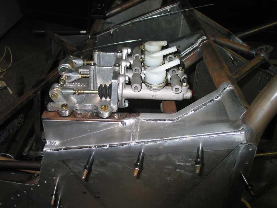
Sept 8, 2002. Drilled rivet holes for the passenger-side wheel well. Cut, trimmed, and welded paneling on each side of pedal assembly. These were tough panels to make, requiring three pieces because of the compound bends. Tilton pedal assembly in place so you can see how the panels fit up. I originally wanted a pedal assembly with forward facing master cylinders to keep brake fluid from dropping on my feet and to move the CG forward. Unfortunately the assembly geometry was different enough that it wouldn't fit with the suspension rocker so close, so this will have to do.
Paneling, pedal area, driver's
right. The vertical portion of the panels help triangulate the pedal
assembly.
The next piece to make is the center panel under the pedals that will
have slots for the pedals to go through. It would be nice to keep it
fully sealed to keep out dust, don't know if I'll find appropriately
sized bellows-type seals which will fit.

Sept 22, 2002. Footwell, front view. Finally finished the three pieces on top of the pedal area that took a long time. Kind of an odd camera angle but you can see the center panel with the holes that just miss the pedals. Cardboard in place for sizing the final passenger compartment panel with cooling pipe cutouts. There will be another large hole in the middle for the gas filler hose connecting the way-cool sport-bike style filler cap down to the fuel cell.

Footwell, driver's right. Too hot to work, took the dog for a truck ride instead. What to do after finishing the top panel? Not sure really. The body shell will be needed soon to add sealing panels from the frame to the shell (looks like the shell *will* be carbon.) Or I can start wiring... or do the hydraulic system, or the dash. Or the shifter... The first go around will be a traditional type, though we have in mind designing a mechanical sequential type at some point. That's for later - need to get this working first. I don't want to get drawn into another time-sucking side projects...

Oct 3, 2002. Invited to dinner by a good car friend, who was meeting his good friend and wife from England. I knew his British friend was into cars, but I didn't realize Who he is. When he told a story of working for Colin Chapman, my jaw dropped open. He worked with Colin designing F1 cars in the 60s! I felt honored being able to speak to someone so involved in racing in that exciting time. We spoke about this car project, and I mentioned for example how, for months I agonized over front and rear roll-center height. He asked what the car's use would be, and when I said autocross and time trials, he pointed out that it should be stiffly sprung enough that roll-center wasn't that critical. I could have talked to him all night long, and wish I could have met him before designing this car, as it was sometimes lonely making design decisions. I'll remember this dinner for a very long time.
Oct 6, 2002. Finished the last foot well panel. Bending the flanges on the hole and slots was fine, though were made worse by being lazy. Confirmed that, yes, the right way is to make a male and female hammer-form. I tried just using the female side, time wasted, lesson learned. Annealing is a wonderful thing as it sure makes the aluminum soft. I could make many of the bends with just hand pressure. The down side is it made the aluminum so soft it gummed up the die grinder, doh!

Flange close-up. It came out pretty well. Not so pretty on the back... but who's going to see... The large top hole is for the gas filler hose. The next project will be the shifter, but I'm pretty picky about stuff like this - it has to be right or it'll drive me nuts. It has to be better then my old Mustang GT shifter. *Everytime* I shifted that notchy tranny it bugged me. Now I have a chance to do it right. Big words from someone who hasn't made one before... we'll see.

Oct 13, 2002. Two CableCraft push-pull cables will translate the x-y motion of the shifter to operate the H22 transmission. To figure out the shift cable routing most of the major rear components were reinstalled. The white wire was some that was laying around and it worked well for determining routing. The cables run under the pan - so there's no worry about them getting cooked by the exhaust (see below.) If it couldn't go under the pan it would have been much longer and have at least three more 90 deg bends. With only one gradual compound bend, it should operate smoothly.

Trying to figure out exactly where the shifter will go - note high-tech wooden dowel shifter. It's a little tricky because the cables are needed to try various shifter designs... but I also need to know the exact distance from transmission to shifter before ordering the cables, which I need to test designs....

Looked at the shifter in the Honda Service Manual and wondered why I was trying to reinvent it. Honda's are known for their excellent shift feel and a used assembly was only $65. I'd spend that much on spherical bearings along, never mind my time - so I bought one. Shown is the stock unit before modification. I just know a women owned the car this came from. It reeks of perfume!
Oct 20, 2002. The Honda shifter frame was cut down leaving only the actual shift mechanism. Shown is the reversed-and-flipped-over shifter assembly in place minus the shift lever, to be welded on later. The mock up is for measuring cable lengths. It's a bit tricky because the shifter linkages move far more than they will once attached to the tranny, so shifter placement will have to wait for the cables. Once I have the cables I'll determine the shifter's permanent position then determine the shift lever mounting.

Oct 23, 2002. Received the
push-pull cables. What's disappointing is how the cable operates when
it has a curve in it (and when wouldn't that be?) The inside sleeve can
be felt moving sideways within the outer shield, introducing about 1/8"
of backlash. I am told all cables of this type do the same thing;
unfortunately that little 1/8" is going to get magnified once the shift
lever is connected. Looking at the cutaway view of the cable... it
looks like I could inject something like RTV between the inner and
outer sleeve, fixing the two in relation to each other. Perhaps later,
after I see how bad it is in actual operation.
Oct 27, 2002. Reworked the stock Honda cable bracket on the
transmission, as the mounting faces needed to be moved away from the
transmission by about one inch. Shown are the new cables in the
modified bracket. Still need to make bushings and clips for the new rod
ends. Testing will proceed when the bracket at the shifter end is
complete.
Nov 3, 2002. Shifter design continues. Have preliminary shifter base
tacked together and am about ready for initial mounting and testing of
entire mechanism. This is taking far longer than expected, but it has
to be right, else it'll drive me nuts every time I shift... Pictures
when it's complete.

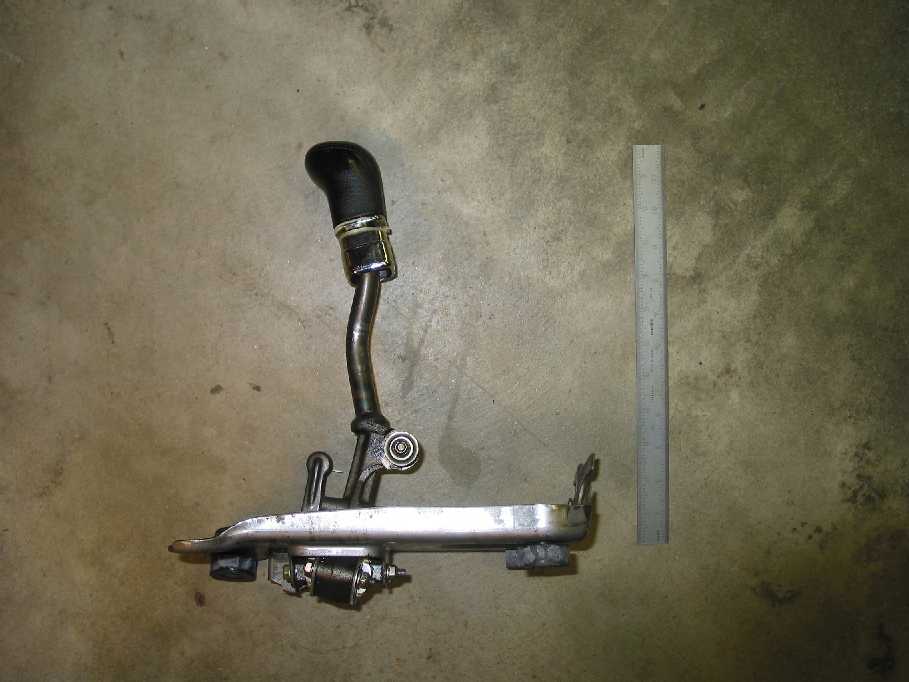
Nov 3, 2002. Finally!! Finished the shifter by throwing a lot of time at it. Here are a couple of shots of the final configuration. Though it took a long time I'm pleased with how it turned out, there isn't much free play, and the throw is much shorter than stock

I placed both hands on the steering wheel, closing my eyes, and moved my right hand to where the shifter “should be.” That’s how “scientific” placement was, but it turned out great. Not even thinking about where the lever is, and my hand just ends up right on it. What’s not shown is how the shifter ended up aligned with the steering wheel. I only noticed it after it was done, but if a plane is projected through the rim of the steering wheel, it passes right through the shift knob. A possible design “rule of thumb?”

Nov 10, 2002.
Add hold down brackets for the fuel cell. Even though it was well boxed in, I never finished the actual "bolting down" part of the fuel cell install. The problem is having a full 70lb fuel cell sitting directly on the thin stainless floor - it seemed like asking for trouble. So I added two brackets, one near the shifter, and a removable bracket at the front, which attach to the existing bolts on the top of the cell's can. The front one is removable so the cell can be easily removed for service. With the brackets, the cell is now suspended slightly above the floor, removing tension off the rivets. This also solves the problem of spilt liquids. I was afraid it could pool inside and around the bottom of the cell, with no way out. With the cell flat on the floor, the liquid could sit down there a long time. Now I can put a couple of small drain holes at the back corners under the cell to let out any spillage.
What’s next. Having just finished dealing with the shifter cables, I'll probably do the gas pedal and throttle cable. After that... electrical. There’s also a growing list of things “almost done.” These drive me nuts because various sub-assemblies aren’t truly complete. I’ll probably go back and finish up a bunch of things after the gas pedal and before the electrical.
Nov 16, 2002.
Initial gas pedal design - almost. As it was, my shoe missed the brake pedal by about 1/16” so another sub-project was adding a boxed section to the tunnel panel to increase foot space. That’s the good news…
The bad news is I had one of my anxiety attacks. Occasionally, and never on purpose, I make the mistake of raising my head from the small part I’m making and, wham, the enormity of the project hits me. When this happens it’s very hard to keep working; the project is just so big, so huge, it seems like it’ll never get done. The shifter took three weeks yet it seemed like three months. I can see the gas pedal taking several weeks easy… geez it’s just a stupid gas pedal, yet this little part - just like every other “little part” - can kill me if it goes wrong. It has to be made right.
Maybe it’s time to start the engine again… But before that happens I’d like the cooling system to be complete, which means adding radiator mounting brackets. But I need to know where the front extreme of the car is… it’s always something. This is part of the reason why it’s good to work on the car only one day a week. It avoids burnout and forces “timeouts” in order to get my incentive back.
Off topic but interesting. A friend builds Cobras as a side job. He confirmed what I said about kit cars, that many manufactures design in all the short comings of the original (why!?) He said the 427 version is great for getting attention, but you’d never want to go around a corner fast because it flexes so much… just like the original. At the time trials at Riverside Raceway, a guy used to show up in a Cobra kit car. In a straight line he’d leave me way behind, yet the thing was so squirrelly in the corners, causing him to slow down so much, that I’d catch right back up, in a Datsun 1200! Yeah I know the Cobra was technically faster than mine, but that’s tough to argue when our lap times were the same. It was so terrifying to the driver, he couldn’t use its full capabilities; so was it a faster car or not?
Nov 24, 2002. Stopped by an off-road shop to check out their gas pedals. Eh, they’re only “okay.” I’d have to modify them anyway so I’ll do my own. And no, I didn’t buy the chrome-plated pedal in the shape of a foot, complete with toes! So today was spent building the pedal pivot and arm, next week will be the pedal itself. I got distracted by the fuel cell though because some fool (me) installed it offset by 1/8”. 1/8” is a lot in a little car like this one, and it kept the steering rack from going in. Crap, there’s only one thing worse than spending too much time on something, and that’s building something wrong, and having to redo it. It’s not so much the material cost as the time spent, twice. Anyway, I redid the mounts which ate up the rest of the day. Nothing worthy of pictures.
As I said before, there’s a nagging list of sub-assemblies “almost done.” Whiles it’s fun to work on new parts, and gives a great sense of progress, they aren’t really done until they’re really done! So pretty soon I’m going to have to step back from working on all these cool new parts and literally take care of some “unfinished business.”
I also recently learned what it must be like to build a car in England because a couple of weeks ago we had a rain storm complete with wind. The wind blew the rain into the garage through a wall vent, which was no big deal. I mean, it was only maybe a cup of water. But that little cup of water evaporated and then really attacked the steel chassis. The chassis has been somewhat rust free the last five years, but in the last few weeks it’s become much worse. Time to rub it down with an oily cloth. It isn’t something I really want to do however. When I asked the powder coating shop how they prep metal, they said they sandblast it. Then I asked how they degrease it. Apparently they… don’t really. I have a hard time believing that because what about the sand dust and oil film? Anyway I’m concerned about the oil I rub on getting inside the tubes, then coming back out when the chassis is being baked after powder coat (not to mention the sand also.) We’ll see.
December 1, 2002. Gas pedal in process. The cutout on the right is for my huge foot (behind it is the fuel cell.) The cutout also provides a convenient “port” to get the throttle cable from inside the center tunnel out to the foot well, otherwise an awkward transition. The gas pedal is the goofy looking thing resting on the red shop rag. The bent tube on the far right will pull on the throttle cable, while the long straight tube (not cut yet) will be welded to the pedal. If the throttle cable is simple attached to the right-side flange of the pedal (using only one tube), it would twist slightly in operation. Using two tubes separates those functions so the pedal won’t feel funny when depressed. At least that’s my thinking now… I’m sure a year from now I’ll wonder why the heck I did it this way. Anyway I stopped working on it when I realized gas pedal appearance matters - an ugly one simply isn’t allowed. So I have to decide what it’ll look like, what material to use, size, shape, that sort of thing. So I moved on and measured the required throttle cable length to order this week. I’ll either just call a hot rod shop and have one made, or go to a good bicycle shop. I’m told cables on quality bikes are very nice Teflon lined parts. OTOH, if I decide on a push-pull cable I’ll have to use the same source as for the shifter cables. The advantage of a push-pull throttle cable is if it ever gets stuck open, I can pull the pedal up with my foot, forcing the throttle closed. After taking measurements I finished the front removable fuel cell bracket, not worthy of a picture.

December 7, 2002. Installed the new throttle cable. The cable fits fine though I’m not impressed with my gas pedal… I might redo it or at least modify it. It’s one of those nagging things… is it good enough and time to move on, or does it need to be “just right”. Read that as, “potential time sink.”
A mechanical engineer friend looked at this site and said, “it looks like you’re walking a fine line between decent design and getting it done.” I guess I’m trying to do just that. Take for example the V8 914 project listed in Other Builder’s. By his own admission the builder has spend 17 years and 18,000 hours on it - yes, that’s three zeros. That is Not me. I like building but I want to drive my car before it rusts away and I’m too old!
December 8, 2002. Various tasks. Modified gas pedal to “good enough” status. Determined where to cut the hole for the steering shaft to pass through the foot well. Looked through the Minor Rubber catalogs to find a shifter boot and some H-section molding for the Lexan window which will go in the rear bulkhead, above the engine. Might as well get these ordered in case they take a while. Stared at the radiator thinking about how to mount it. The secret is to hold it with rubber lined brackets, avoiding any rigid mounting. Stiff as the chassis is, it will still flex, and a hard mounted radiator will crack.
Okay, okay, here’s a couple pictures. This shows the alignment of the shifter with the steering wheel. As I said earlier, I was surprised it ended up perfectly aligned. The shifter is in the neutral position.

December 9, 2002. Minor Rubber does not get my business. It was a typical scenario, call a huge company and try to order One of something. Yeah they’ll sell me one rubber boot… for $140! I bet 1000 of them would cost $141. Guess I’ll just order an aftermarket leather boot perhaps with a matching shift knob.
I remembered I have threaded ball joints on the steering shaft and wondered if I had the lower one screwed all the way in to give my feet more room. No it wasn’t! Good news… so I screwed it all the way up and now it’s perfect. I was a bit concerned that I might get my foot jammed under the shaft. Good to get that out of the way.
Dec 15, 2002. Radiator duct design. To the right is the beginning of the cardboard mockup for ducting air out of the Griffin radiator and up and out the center of the hood. The reason is I didn’t want the exiting air going down the center tunnel and heating the fuel. I also didn’t want it exiting under the car, decreasing downforce. It remains to be seen how efficient it will be. I feel it will work if the exit vent is toward the front of the hood, away from the base of the windshield, a high pressure area. Of course the Mini hood is very short, which means I may have trouble getting the air out. If this is a problem I’ll add additional exits out to the backsides of the wheel wells, which is how many race cars exit radiator air. I’m guessing it will work because the radiator is large, and there’s no drivetrain right behind it blocking air flow. In my Books link is the aerodynamics book by Katz which was extremely helpful for designing the ducting. Below are a side and top shot of the nearly completed mockup. It’s a tight fit in there with the suspension, fuel cell, and steering rack. The radiator pipes just fit between the ducting and the suspension rocker arms.

Dec 25, 2002. Hey give me a break, it’s Christmas! Working on the radiator support brackets which aren’t trivial due to the needed compliance. I have the hardest time making a bracket simple and elegant. Sure I can make them, but they always seem, well, Neanderthal-like. After it’s done I can always see how to make it lighter, stronger, and simpler, but that’s the nature of design and fabrication. Like I’ve said before, by the time I’ve built ten Kimini cars, it’ll be perfect!
Ordered a Suzuki factory service manual on CD for a Hayabusa. Doesn’t hurt to look, hee, hee.
And don’t drink too much this holiday, I lost a good friend to a drunk driver…
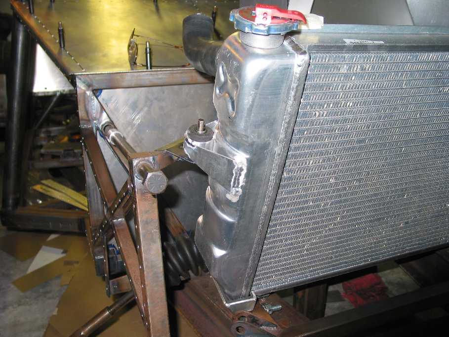
Dec 29, 2002. Finished the radiator mounts, which took a surprisingly long time because of the rubber mounts. Welding aluminum reminds me of playing a computer game, except you aren’t allowed to start over. If it goes wrong, most of the time, that’s it, game over. In the picture to the right you can see the rubber bushed side mounts. (The rubber bushings were laying around from the Honda shifter I bought.) The aluminum “cups” at the bottom are rubber lined also. Ordered AN-series suspension bolts from Aircraft Spruce. Bent the ducting for the radiator exit air, though it still needs Rivnuts. The ducting is purposely left extra tall since only when the nose is in place will I know exactly where to trim it. Put the brake and clutch pedal cluster back in and found the gas pedal is too close, so that’ll need fixing.


What next… There’s still much to do, but the list is getting shorter. Brake and clutch lines. electrical system and dash, skinning the undertray below the engine. Probably start the hydraulics with something simple like the clutch… or the dash would be fun…
Dec 30, 2002. Measured out the brake and clutch line lengths, then went out and had them made up - very expensive. Why don't people use hard line on sports/race cars? Production cars do so why don't I? Two reasons, I don't have the flaring tool, and using hard line means buying an additional fitting and adapter at each end, negating any savings unless the line is fairly long. So I used Teflon line throughout. I do admit that it rates high on the “cool” scale.
`
Dec 31, 2002. My thoughts go out to a good friend who just underwent colon cancer surgery. Reminds us all how petty our “problems” are and what's important in life.
Install front brake lines and mounting brackets. Finally showing a overall top view of the front end instead of the “micro pictures” I keep taking. Not a great angle but you can make out the front brake lines. The routing worked out really nice and came out perfectly symmetrical. It isn't bragging, sometimes I'll make some little part, and it comes out... how do I say this... better than I deserve.
I don't know if others do this, but I make cable mounting brackets by welding a #8, 1/2” stainless flat-head screw “head down” to a chassis tube. This gives me a permanent stud on which to put rubber-lined hose clamps. The clamp itself is held with a nylon-lined lock nut and washer. Seems simple to me since it eliminates one loose part. Since the stud isn't structural and isn't disassembled often, it's unlikely to strip out. Easier and simpler than using a Rivnut. I'm sure someone will now point out a big flaw I haven't thought of.
Which reminds me of something I told someone recently. It isn't the stuff I've thought of that worries me, but the stuff that I haven't thought of yet...
